The T-Rex
By Bradley Walker
Note: Dedicated to the late great Big Jim Greenaway (“The Source”)
I received the first prototype of my new T-Rex 60 design in December 2007. This is the initial offering from the Brodak overseas factory for the new Brodak “component kit” (ARC/ARF) that is scheduled to be released in late 2008.
The T-Rex is a completely new design and is completely original as practically possible in the world of control line stunt. The design does have obvious linkage to Bob Palmer’s Thunderbird. Of course, that was always the intention. Even the T-Rex name is a play on the Thunderbird name (T-Bird/T-Rex…get it?).
One of my favorite stunt planes ever published was the Tom Dixon “Thunderbird 60” (Model Aviation 1988). Even in black and white as published, I just thought it looked so beautiful, and yet it, still looked so “mean” with its simple shapes and sweeping elliptical lines. When I started to design a plane for Brodak Manufacturing I wanted something that would appeal to the “classic” stunt enthusiast, as well as the “modern” stunt enthusiast. I thought a totally modern Thunderbird with European accents might be an ideal mix. So far, I can honestly say I am happy with the choices! Also, I like to think that Mr. Palmer would have liked the thought of a T-Bird for the next millennium.
Stunt Plane Aerodynamics for Aerodynamic Dummies (Like Me)
Let me just say, the following view of stunt plane design is based on MY OPINION and as much practical information as possible.
I have been designing and building my own airplanes since 1994 (I have been drawing my own stunt plane ideas since I was kid). I know, I know…compared to Billy Werwage I am a puppy, I accept that fact… I have drawers full of plans from stunt planes from many eras, and I have spent hundreds of hours measuring, comparing, and overlaying paper plans. In addition to being a stunt enthusiast, I have also been designing, consulting, and publishing as a mechanical engineer for 15 years. For more than a decade, I used AutoCAD 2D exclusively to do all my professional design work (I have recently switched to 3D solid modeling). As an AutoCAD enthusiast, I have had a lot of access to CAD stunt plans as they were produced. I have also scanned paper plans into AutoCAD and overlaid those plan scans for study. CAD also gives you the ability to scale plans of designs from different sizes and overlay those with larger/smaller airplanes for direct comparison. So, long story short, I have examined a lot of stunt plane plans!!!
From all of this exposure, I have come to two conclusions:
- Within a given envelope and for a given scale, most of the modern stunt planes in use today are all very similar dimensionally and aerodynamically.
- To a large extent, all of the aerodynamic design elements commonly in use today have all “been done” at one point or another.
All airplane designs have elements that are different, obviously. Everyone wants to put their signature on their designs, and as the old saying goes “the devil’s in the details”. I do know that tiny variations in dimensions are often the subject of heated discussions within the stunt community. It is not an uncommon view that these tiny variations will “make or break” the capability of the design to perform properly. For example, someone might make the horizontal stabilizer chord in their new design a ½” longer than used in the previous design, and then declare a design victory because the new design “flies better”. Similarly, another flyer might change the rudder shape or wing tip shape on a competition proven design and be told that the design is “ruined”. Truth be told, stunt planes are hand built custom creations made out of less than consistent materials. Control line stunt planes are not milled out of aluminum or steel using precision machinery. They are typically made from wood and foam, and for the most part, are assembled “in the air” or on tables using primitive fixturing. There are thousands of design elements, trim elements, and construction variations that could affect the performance between one airplane and the next. When comparing these elements, we simply do not have the capability to isolate these elements and know “what is affecting what”. So, just between you and me, if anyone claims they can tell the difference between two airplanes solely based on a ¼” dimensional variance here and there, they can also most likely feel a pea under a stack of mattresses.
That being the case, I just cannot get too excited about picking small dimensional changes within the classic standard, even though I am always interested to know why something is being changed. However, it is also important to note that from my experience, those designers that make the mistake of overdoing design elements, or going to far afield of the “classic basics” nearly always create designs that have “issues”. Ask me how I know! Typically, the most simple and basic “centrist” designs are the best designs. Interestingly the “centrist” designs tend to be the most popular and have the most longevity. I think this is a refection of the KISS principle (Keep It Simple Stupid), which is a universal truth.
For the most part, the lineage of most successful modern US stunt designs can be traced to fall somewhere between two classic schools. On one side would be the “classic era” standard of the Nobler/Ares the 1960’s (low aspect ratio wing, smaller tail surfaces, short moments, thin wing airfoils), and on the other side would be the futuristic looking jet style “foam clone” standard of the 1970’s (high aspect ratio wing, larger tail surfaces, long moments, thicker airfoils). It appears that as a result of airplanes increasing in size in the 1970’s, changes were made in the design of the 1960’s stunt ship to accommodate the increased weight and power. Even to this day, most modern stunt designs have elements that fall somewhere in between these two extreme standards, or borrow elements from both, with only minor dimensional stretches to give the designs individuality.
In terms of aerodynamics, the goal in designing the T-Rex was to design a plane that would not have any “funnies” or strange tendencies, would be fast to trim, and easy to fly well for just about anyone who picked up the handle. Everyone must realize that flying the pattern is a compromise. In the execution of the stunt pattern, there are hard corners, straight legs, round rounds, smooth transitions, and, if the judges are doing their job, all aspects of the pattern are judged equally. Designing for one aspect of the pattern will always sacrifice some other aspect. The one universal truth in stunt flying is that an airplane that can be easily trimmed and will “go where you point it” will always produce the most consistent results than a design that is riding the ragged edge of performance to gain a competitive edge and the flyer “dare not take an eye off of it”. It is also true that a high strung design with “amped up” trim settings can do well in the hands of talented pilots, but a design for the masses would make everyone look good and would not “do anything unless you tell it too”.
My favorite stunt planes are so beautifully stable they nearly fly themselves in level flight, fly consistent rounds one on top of the other seemingly with a single input, fly a sharp corner equally in both directions with the least roll and yaw “drama”, and then exit the sharp corner very flat and predictably. In my opinion, the sharpness of the hard corner required for the pattern needs only have a sufficiently small radius as to be “middle of the pack” competitive. Given the current state of judging and scoring, it is my opinion that over the long haul, a pattern flown with consistent shapes, exits, and overall smoothness beats a pattern flown with hard corner “flash” with any crooked legs or bobble mistakes. I simply do not see contests being held where judges are being coached to award “bonus points” for flyers that execute sharp corners or nearly impossibly small rule book maneuvers (it could be argued that they should, frankly, but that is another discussion altogether). At the same time, I do see flyers performing in contests being penalized for bobbles, crooked legs, or inconsistent bottom heights even when they are flying the maneuvers more correctly than other pilots that are flying “smoothly and accurately”. From my observation, bobbles, bottom heights, and overall maneuver shape are easy to see and are the first things judged. Conversely, maneuver size, and intersections are the HARDEST elements to see, so they are usually not the primary criteria used for judging. Lastly, there really are no bonus points set aside for impressive corner radius. Pilots are not rewarded for flying excessively sharp corners, and they are penalized for trying and slightly missing.
There are elements flying a control line model of which I am absolutely, positively sure:
- Under completely normal circumstances, if the lines to the model are tight, you have control of the model (we call this “line tension”).
- If the lines to the model are loose, the pilot does not have control of the model.
- Most of the stunt pattern is judged in the downwind segment of the hemisphere.
- The wind blows at different speeds and will effect the plane in flight like a kite
What do these elements have to do with “aerodynamics for dummies”? I am glad you asked! The last thing you want designed into a stunt plane is the tendency to yaw inward. (Note: yaw is the hinging of model in the same plane as the lines, or “tail wiggle” as it is commonly called). When flying a stunt pattern, any yaw is bad really, but outward yaw is better than inward yaw. Inward yaw (the nose moving to point toward the pilot) at the wrong time could not only lower your scores, but could ruin your day completely if the plane decides to fly away under its own control and not your control.
In the effort to eliminate yaw as much as possible, the main challenge to the stunt plane designer (in my opinion) is to eliminate what is called “weather vaning”. Weather vaning is simply wind induced yaw. The typical shape of a stunt plane, with its large rudder and small nose (like a weather vane or a “lawn dart”) can actually exacerbate weather vaning. A stunt plane designed with a large rudder and small frontal side area will have the tail blown away from the pilot on the downwind side of the circle when flown in the wind. If this imbalance of large aft side area and rudder to small frontal side area is great, this effect will increase as the wind blows harder. There is no more sick feeling in the world than flying a side area imbalanced airplane in a gale and attempting to enter the top loop of the vertical eight, and the wind gusts. As soon as the gust occurs you KNOW the rudder is going to catch the gust and the airplane is going to yaw in at you at the worst time (like when the airplane needs to bore back into the wind). Ask me how I know! When flying in high winds, not only will the airplane feel light on the lines in the oddest places, it will most likely fly like it is horribly out of trim or will feel like it is going in and out of trim. This is due to the fact that wind induced yaw, both in and out, is constantly changing the flying attitude of the airplane. This weather vaning of stunt planes could do a lot to explain why there are a lot of stunt flyers that suffer from the “my motor is too small” effect when flying in bad conditions. Of course, it is possible to do what a lot of the top flyers do to overcome the weather vaning effect, which is to fly so fast that the line tension is so great in all areas of the hemisphere that wind induced yaw has little effect. While this does work, I do not recommend it without a substantial amount of practice and exceptional hand eye coordination (and a monster pull test).
In a perfect world, a stunt plane would have an equal amount of side area in front and behind the leadout exit, or more specifically ACT (in a dynamic fashion), like it has balanced side area in front and behind the leadout exit. When designing stunt planes, I suggest adding a little more side area in front of the leadout exit, not behind. I also suggest making the rudder as small as practically possible. A little extra side area in the front of the airplane and a little less at the far end of the rear will help ensure that the wind will blow the nose away from the pilot when downwind. If anything, the line tension will increase as the wind blows harder and harder, ensuring that the pilot would have adequate line tension to bore through the wind under control at reasonable speeds. I suppose that in the case of the large frontal side area design, the argument could be made that inward yaw could be bad upwind, but I simply do not see that concern showing itself on the scoreboard. Except for the entrance to the wingover and overhead eight, there are no upwind portions of the pattern being judged, so why design for it?
With all that said, the T-Rex is very “bread and butter” aerodynamically. Aside from the less common Palmeresque elliptically shaped surfaces and non “lawn dart” fuselage shape to maximize usability and minimizing weather vaning, I can honestly say there is nothing “out of the ordinary” about the numbers used in the design. I do believe that this “middle of the road” design approach will produce the best results. I define “best” as being easy to fly and trim, and then provide predictable performance in good and bad conditions alike. To this end, the T-Rex is of moderate size and weight and uses a 675 sq in moderate wing aspect ratio symmetrical wing. The wing has a root chord of 10.75” with a 2” taper to the tip with a medium thickness wing airfoil with a moderately rounded nose section, a 10 ¼ inch nose moment, 18 1/2 inch tail moment, 20% wing flaps, 23% stab and elevator, and a 55%/45% stab to elevator ratio. This dimensional combination will result in a trim CG of approximately 18%-23% of the Mean Aerodynamic Chord depending on which power train is utilized.
If it helps to have an aerodynamic reference, the T-Rex is a mix of the Bob Palmer Thunderbird II, Tom Dixon T-Bird 60, Big Jim Greenway Patternmaster, Bob Hunt Saturn, Randy Smith SV-22, Paul Walker Impact, Billy Werwarge P-47, Brett Buck Infinity, Bill Wilson Hunter 7, and the Bradley Walker Dr. Jekyll/Mr. Hyde and Valkyrie…Does that help?
A Monkey Wrench Look at Wing Loading and Scale
The most radical change for the Open Class stunt ship since the 1960’s “classic” Ares/Nobler standard has been the overall size of the airplane and the wing loading. For whatever reason, it is commonly whispered in stunt circles that the modern “open class” stunt ship must be relatively large to be competitive, or at least APPEAR to be large. I do not believe this, but many people do believe this and propagate this idea (I pretty much believe that it is the pilot that “collects the brass” not a particular airplane).
Most people do not realize how weight and wing loading relate to airplane size. After spending many hours scaling planes in CAD, I have a much better idea how these factors relate. There are three dimensional relationships that one must contend with when scaling designs: linear, area (squared), and volume (cubic). When scaling relative to a linear dimension (say the wing root dimension) the area (say of the plan view of the wing), will change to the square of the change. The volume of the same wing will change to the cube of the linear change. Weight in stunt ships is typically a function of volume and surface area. These are cubic relationships to the linear change.
Let me try to explain this with a very simple example. Picture a cube of foam that is 10” on a side. The foam block is 10” x 10” x 10”. The area on one side is 10” x 10”=100 sq inches. The total volume of the cube is 10” x 10” x 10”=1000 cu in. If we give the foam a density of 1 oz per cu in, then the cube will weigh 1000 oz. If we give the block a weight to area to loading (this would be the same as the pressure that the block exerts on the ground when you set it down) we would divide the weight by the area 1000 oz/100 sq in=10 oz/sq in.
Now let’s scale the block to 90% to the linear dimension. Now the block will be 9” x 9” x 9”. The area on one side is 9” x 9”=81 sq in (81% relative to the original). The volume is now 9” x 9” x 9”= 729 oz (73% relative to the original). Now the weight loading of the block is 729 oz/81 sq in=9 oz/sq in. So, as this simple example explains, if the same plane is scaled down the projected wing loading goes down (or said another way, becomes relatively easier to achieve).
One last item in this weight relationship is that nearly all of the building material in a stunt plane is near the surface of the airplane. This, obviously, also includes the final finish. The surface area equation is typically a multiple of the area. In the cube example, the surface area is one side of the cube multiplied by the six sides. To calculate the surface area we use 10” x 10” x 6 sides = 600 sq in. If the cube is reduced to 90% as in the previous example, the surface area would be calculated as 9” x 9” x 6 = 486 sq in. Therefore, this reduction of 10% in the linear dimension results in surface area reduction of nearly 20%!
With all that said, airplanes are obviously not made from cubes, and the surface area equations are most definitely complex for aircraft than for a cube, but I think this elementary example serves to show that surface area is not a dimensionally linear function.
As a practical example, let’s look at three stunt plane design examples:
- Airplane #1-Let’s assume we design a plane that is designed for a modern .61 sized engine around a wing of 650 square inches of wing area (this is the actual 2D plan view square inches of area of the wing as measured in CAD). As a reference, this is nearly exactly the same size as the Saturn, Bear, and SV-11, all of which are very common designs. Let’s say we build this plane at the ultra light weight of 56 oz or 12.41 oz sq ft. (this is not a typical wing loading for airplanes of this size, most typically, these designs will build to more than 60 oz or 13.3 oz sq ft. plus)
- Airplane #2-Now we go into CAD and scale the same design to 90% of the linear dimension to make a 40 sized stunt plane. This means that all of the linear dimensions in the 2D drawing will be 90% of the original (10” nose moment=9”, 10” wing root=9”, etc). Now the wing that was 650 sq in of area at 100% scale, when reduced in the linear dimension to 90% of the original now has a wing area of 526 sq in (.9 x .9=.81=81%x650=526). So, to get the same super light 12.41 oz per sq foot wing loading used in the 650 sq in airplane, it would need to build this new 40 sized plane at a weight of 45 oz.
- Airplane #3- Now we go into CAD and scale the same design to 80% of the linear dimension to make a .25 sized stunt plane. Now the wing that was 650 sq in wing at 100% scale, when reduced linearly to 80% of the original has a wing area of 425 sq in (.8 x .8=.65=65%x 650=425). So, to get the same super light 12.41 oz per sq foot wing loading used in the 650 sq in airplane, it would need to build this new 425 sq in design at 36 oz.
Hmmm… that can’t be right.
In the case of Airplane #2, this new 40 sized design is nearly exactly the same wing area as a Geiseke Nobler. 45 oz for the finished weight of G. Nobler is not “lightweight”. Per Bob Geiseke (who is a “weight freak” by the way) the G. Nobler should weigh 42-44 oz to “fly right” (11 oz per sq foot). Interestingly, this 11 oz /sq ft wing loading is not difficult to achieve in building the G Nobler, and much lower weights can be achieved. In fact, this is a completely attainable weight and is very typical of the UHP laser cut kit airplane weight. In fact, the prototype of the new UHP “component kit” of the G Nobler came in at 42 oz with a painted finish! All this with no changes whatsoever to the design or construction. Also, my very typical Brodak Vector ARF with an LA 46 is 42 oz at roughly 560 sq in of wing area (10.8 oz per sq foot).
In the case of Airplane #3, a 36 oz stunt plane at 425 sq in would typically be considered a “real porker”. For reference, the last Nobler ARF I flew with a Brodak 40 was 38 oz at roughly 540 sq in of wing area (10.13 oz per sq foot) and it felt like a feather and jumped out of the corners like a combat plane. The Nobler was certainly not heavy.
The truth is that weight to size is a tricky relationship, but I can guarantee that the larger the design the harder it is going to be to build at the same low wing loadings. If you choose a wing loading based on a smallish design and expect to build a much larger version of the same airplane at the same wing loading, you are in for disappointment.
I hope this shows how construction type, material, size, and type of finish all relate to the ultimate weight. Remember this as the design of the T-Rex is discussed…
Designing the T-Rex
I take great pride in the fact that the T-Rex is a brand new design. The fact is that most “modern” stunt planes that are kitted today are typically 15-20 year old designs and some of the most popular kitted designs are older than I am by quite a bit!!!
The T-Rex was designed from the ground up to be laser cut, mass produced, and flexible to any type of engine in nearly any kind of configuration (2 stroke or 4 stroke type, side mount, inverted mount, 45 degree mount, side exhaust, rear exhaust, tuned pipe) . It was also important to create a design that could be successfully finished in a paint finish and not be a “porker” for weight. The ultimate goal was to produce a plane that would fly as well as a scratch built competition ready plane (that would cost substantially more to build). This is a lofty ultimate goal, I know. Only time will tell if the design comes close to this lofty goal, but everything possible was done to try to get there!
Every consideration was given to the fact that nearly all successful modern CLPA competition airplanes are made from 4-6 lbs density “contest” balsa wood, and a lot of it. If you pull out your collection of plans, many of the modern airplanes were originally designed around the nearly exclusive use of light wood throughout, and to lesser extent, exotic materials like carbon fiber. When these same successful designs are built with standard “hobby shop” wood of even good quality and only slightly higher weight, the overall weight of the plane skyrockets, and the plane no longer performs well.
It is simply a reality that mass produced airplanes are not made from this very rare type of “contest” balsa wood. Early on in the T-Rex project, I tried to make “contest wood” mass produced airplanes a reality. It became apparent as the project progressed that trying to produce planes from “contest wood” exclusively would to be a dead end, so the idea was dropped.
Fortunately, for the T-Rex, several design solutions presented themselves:
When considering airplane weight, the first thing to do is to eliminate anything that has weight in the design that does not serve a specific function to improve performance. The first thing on my list of things that serves no function in terms of flying stunt patterns is the propeller spinner. Frankly, a spinner is just for looks and (for me) usually creates more heartache and frustration than anything else. Nothing is uglier to me than a plane that has the spinner misaligned (which is why a misaligned spinner is often the reason that trim of the engine thrustline is not considered). There are many stunt planes based on real planes that do not have the standard “lawn dart stunt plane” spinner look, so I decided that was the direction I would take. Ultimately, eliminating the spinner on a stunt plane design this large equates to a 1 oz to 2 oz weight loss without any loss of functionality.
I spent some time in 2007 testing RC type nylon engine mounts and found them to work wonderfully. I honestly have no idea why these common “hobby shop” RC mounts are not used more often in stunt as they are light, easy to find, cheap, easy to use, cannot fuel soak, isolate vibration, accommodate mounting at any angle, make changing engines with different bolt hole patterns easy, etc, etc, etc. So, the decision was made early on to design the T-Rex with RC style engine mounts.
Since RC style radial mounts are to be used, there would be no need for the “Nobler style” double maple engine mounts. These double beams typically determine the width of the fuselage. Without them, the fuselage could be easily made wider to accommodate a more inboard tank position to control windup in the wind as found in the “seriously killer” Yatsenko designs. As a positive side note, using RC style mounts eliminates the need for aluminum mounting plates for the engine for the maple beams. This elimination of the aluminum pads results in another ¾ oz weight loss.
Finish Affects Design
In the past, I had always designed my airplanes to be assembled from “cores” of either foam or balsa wood fully sheeted in very light contest wood. Traditionally, I never liked “open bay” designs because I liked all of the advantages that came with not having to sand and buff non-sheeted surfaces. Sanding a fully sheeted airplane is like sanding a surfboard, and is very straightforward. In addition to the finishing advantages, nothing infuriated me more than poking a hole through a silkspan covered open bay wing (which I did a lot as a kid). I know you must be thinking that there are tougher market alternatives to silkspan for covering bay wings. This might be true; I just never liked any of them! Silkspan, and to lesser extent tissue, are the only coverings I ever liked finishing with, as I found the “organic” materials to be the easiest to use and the most forgiving. Oh yes, I tried the others, but I always went back to silkspan.
Are you ready for a shock? Recently, I began to embrace the use of film for serious painted finish use. I know, I know, I am a traitor that should be strung up from the nearest tree!!! Film is for the unwashed masses of RC flyers and does not belong on a serious stunt ship. NOT FILM!!!! NOOOO!!! Get a rope!!!
A few years ago, I tried the brand name Ozcover film as a base for painting. Ozcover is heavy clear film that is supposed to be great for painting (uh-no…). I covered my Solace design with this film and applied my standard automotive primer, basecoat, and clearcoat finish directly onto the film. While I missed the silkspan in the finish, hated the spotty adhesion, and some of the poor film qualities of the Ozcover itself, I could see a tremendous advantage to the painted film “idea”.
Shortly thereafter I used film for the finish of my “kit bashed” Brodak Strega ARC into the “Valkyrie”. For the “Valk” I used red Monokote as a base for the wing and tail appendages. I finished and trimmed the film with paint without any regard for the fact that it was film, and it worked great. Many people who have seen the Valkyrie up close have commented that no one would even know there was film under the paint job.
Phil Cartier from the Core House (a supplier of CL combat and stunt stuff and all around great guy and innovator) sent me a sample of his SLC film (Super Light Covering) which is very light clear laminating film etched for adhesion. I found this film to be the “friendliest” and by far the lightest film I have ever used. It, irons on like a dream, shrinks at low and high heat, is very tough despite being very thin and weighing about ¼ as much of most other commercial films, and is dirt cheap (a role of 100’ costs about $25). Phil says that the film is great for direct finishing with paint because the surface of the film has been etched for ink printing, and Phil has done many painted ships this way. I am just too much of a “girly man lightweight” to pull masking tape from film in a multi-layered paint scheme. There is no greater sinking feeling in the world than pulling off a layer of masking tape from your nearly completed stunt plane and seeing PRIMER WHERE PAINT USED TO BE! I want a substrate for my paint jobs that I know has absolutely bulletproof adhesion, as my heart just can’t take it.
To that end, I found an alternative approach to painting directly on the film. I began testing SLC film as a “base” for a traditional silkspan finish. I began applying silkspan over the top of the film with water based polyurethane. In many ways, this appeared to work better than anything I had tried, maybe ever. I prefer using water based polyurethane (like the common brand name Minwax Polycrylic) to apply silkspan rather than using dope. Both my wife and I do not like the smell of nitrate dope and thinners, and my workshop is in the house. Did I mention MY WIFE does not like the smell? I have used Minwax Polycrylic water based polyurethane in the past, and I am currently using water-based polyurethane that was left over from finishing our tile floors that literally has no detectable smell. This is huge in my world, brutha!!! It is also thinner, lighter and much stickier than Polycrylic.
Note: Real men use the “stinkiest” finishing method they can find. Some of the most hardcore real men even change to even more stinky processes as they become available. Real mean love to stink, let’s face it… Nothing makes a real man happier than going to the paint shop and saying, “Hey, you got that new SUPER STINKY paint? I can’t smell the old stuff any more; I think my nasal passages are sealed shut with resin”. I guess I am not a real man any more. I like quiche now. I am a huge quiche eater when it comes to finishing…
Unfortunately, I never liked water based polyurethane (WBPU) for doing open bays because I could never get the hang of shrinking the open bays tight. Because of this, I always stuck to fully sheeted planes. Using the film as a base for the tissue solved this problem. Basically, once the plane is covered in film, there are essentially no open bays that require a tightly shrunk paper covering. Applying silkspan type tissue to a film covered plane is essentially like covering a fully sheeted plane.
Initially, my procedure for applying the paper was the same as the procedure used by “The Master” Bill Wilson. The PU is applied directly from a spray bottle onto the dry paper while hanging from the edge of the work table. Once the paper is wet it is draped over the piece to be finished, and the wrinkles pulled out. The paper is then smoothed with the hands and fingers or a brush. Once the paper had been smoothed, the PU was then flashed off with a hair drier, the edges trimmed, and that is it. Once the paper is dried after sitting overnight it is essentially ready for primer. There is no need to fill the paper any past that point because the water based polyurethane did not sink into the wood or paper.
Recently, I discovered a variation to this method that makes applying the tissue even easier. After using 70% isopropyl to clean my polyurethane brush, I ended up with a milky white jar of isopropyl alcohol. On a lark, I used this mix to apply the paper to a few panels. I found this mix of approximately 10 to 1 of isopropyl alcohol to polyurethane to be the perfect material for applying the paper. In fact, this mixture behaves more like dope than water based polyurethane for the application of the paper. The alcohol (unlike water) dries very, very quickly, is much thinner, has sufficient non-water solvent to keep the paper from getting soggy, shrinks the paper tighter, and has more than sufficient adhesion to apply the paper. By far, this mixture is much less messy, sticky, and does not clog the spray bottle tip, trim blade, and scissors. All this, and the mix still has no stink at all. Once the paper is applied with this alcohol mix all that is required is a full strength coat of polyurethane afterwards to adhere and seal the paper.
One thing to note is that these water-based polyurethanes are by far the most adhesive basecoats I have ever tried. Nearly any kind of solvent based finish seems to stick to it like glue. The reason for this is that they are NOT solvent resistant. The best undercoats for painting actually melt a little when solvents are applied. This is why “non fuel proof” dopes like nitrate are considered a universal basecoat for just about any kind of finish.
Using the SLC film as a base for the traditional silkspan finish solution was literally killing “four birds with one stone”. This finishing method allowed me to:
- Apply my typical silkspan base with either water based PU or nitrate dope
- Fix the puncture resistance issues on the open bayed areas
- Completely seal the airplane so that the finish cannot sink into the wood which causes extra weight
- Cover the surface of the balsa in a smooth surface that does not require any fill at all.
These are all good things!!!
In terms of paint compatibility, once the airplane is covered in tissue, the paint used in the finish does not “know” the plane was ever covered in film. The silkspan with PU (or nitrate dope if that is your thing and you are not happily married) sticks to the film like concrete, and the user can still layer and fix the base using the silkspan. I like to use layers of silkspan paper for transitions, seams, divots, etc.
The Final Piece of the T-Rex Puzzle
Now that I had a good solution for paint finishing for open bays, the liberal use of open bay construction could now be used on the T-Rex.
I have been exposed to many of the prototype Brodak ARC’s and ARF’s, Top Flite ARF’s, and even a few of the soon to be released Ultra Hobby Products “component kit” prototypes. I noticed that the designs that used “typical” modern stunt plane construction, although very nice to look at, were all heavy when compared to their “contest wood” scratch built counterparts. I noticed that the designs that were coming in at a reasonable or even very light weight were the older classic designs that were manufactured using completely built up “stick and tissue” type construction that was more common in the 1950’s and 1960’s designs and kits. Using this type of construction, the lack of very light balsa wood had the least effect.
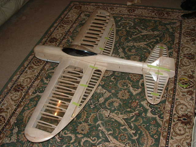
So, to this end, the design of the T-Rex was made open bay “stick and tissue” type construction for all of the major components (basically most of the flying surfaces are constructed like an old “Green Box” Nobler). I now believe this was a very good decision. The prototype T-Rex is the first mass produced type .61-.75 sized airplane that I have been exposed to that even came close to a “contest wood” type scratch built airplane in terms of weight, and the T-Rex is not a small “lawn dart” fuselage stunt plane. It is in fact, a large fuselage design that has a lot more in common with a Bearcat or Thunderbolt than a Nobler.
-60” span, 675 sq inch “actual CAD measured” symmetrical elliptical wing (sized for PA 61-75, ST 60, Saito 56-72 FS, OS Max 52 FS, TT 54 FS). 10 ¼” nose moment, 10 ¾” wing root, 20% flap area, 18” tail moment, 23% stab/elevator, wing mounted landing gears
-Projected finished weight of 60-68 oz with a full pipe or 4 stroke in ARF form. —RC engine mount of any brand (2 stroke or 4 stroke type) side mount, inverted mount, 45 degree mount, etc
-Completely bushed phenolic double suspended bellcrank
-Central Hobbies style pushrods
-All ball link controls
-Tom Morris style control horns
-Laser cut hinge slots for heavy duty hinges
-Lucky box control horn insertions
-Control hatch access to rear control horn and pushrod
-Finished canopy, ready for detail
-Completely covered in Phil Cartier’s SLC film (very light laminating film etched for adhesion) ready for application of silkspan for traditional dope/tissue finish or direct finish onto film
-Two piece wing.
-All laser cut components.
The tank floor has also been omitted to show the I-beam nose structure.
-Removable hatch for control access.
-Finished canopy, ready for detail
-3 1/4 wide front end for inboard tank mounting (like a Yatsenko Shark). Designed to accept RE engine, SE engine, tuned pipe, etc.
-Pre-finished molded fiberglass cowl.

-Lightweight construction.


-Fully bushed and suspended phenolic bellcrank.

-The T-Rex is designed to use a RC engine mount of any brand (2 stroke or 4 stroke type) side mount, inverted mount, 45 degree mount, etc Here you see the Dave Brown 60FS engine mount (retail $6.95). The T-Rex is designed for this mount, as I have tested them and I would not use anything else (at least in 4 stroke length-there are other good alternatives in standard length). I will be suggesting this mount for the kit.

-The plane comes with one 1/8″ firewall attached. This will be the “guide firewall” for attaching the actual 1/4″ firewall. I have attached the mount to a piece of 1/4″ ply that that will serve as the main firewall (this will be included with the kit). I used standard blind nut installation with 6-32 bolts (I really hate working on mounts once the plane is built, so I decided on this method). It is really easy attaching the mounts outside of the plane. The model plane will come with one 1/8″ firewall attached. This will be the “guide firewall” for attaching the actual 1/4″ firewall.

-Here is the whole thing clamped up for fiberglass filled 5 minute epoxy gluing. The finished 3/8″ firewall is more than substantial for mounting the nylon mounts.

-This is the finish tank area. Note the fillets inside and along the engine firewall (they are hard to see as they are light brown). This is fillet mixture is 5 minute epoxy filled with West Systems micro light filler (similar to Epoxolite but takes only a few minutes to use). This not only serves to strengthen the whole installation, it will serve to totally fuel seal the tank compartment.

-This is the engine compartment ready for fuel proofing
-Here is the PA 65 installed.
-Here is the engine compartment fully sealed with Zinsser Bullseye 1-2-3 Water Based Primer Sealer. This is a water based, very fuel proof, brushable product that you can find at any Home Depot. It goes on white and thick and smells like latex house paint. I use this in place of epoxy for fuel proofing engine compartments. Of course, this is another innovation from the Master…Bill Wilson
-Wing panel covered in SLC film and silkspan, ready for primer.
-Wing panel after one coat of Sherwin Williams Ultra Fill spray can primer and sanding.