Bashing the Brodak Strega ARC Prototype
Part One
Being a big fan of the “aerodynamically approved” designs of Big Jim Greenaway, I was excited to hear the Brodak Manufacturing was planning to ARF Windy’s ST60 sized Strega. It was about time the ARF boom in CL stunt had finally reached the full sized designs! I was so “stoked” about the possibility of having a readily available Strega to “bash” (read that modify), I called John Brodak and begged to evaluate one of the pre-production prototypes. John agreed, and had one of the ARC (Almost Ready to Cover) units sent to me. After looking over all of the design aspects of the stock unit, I called John and verified that bashing was an option. True to form, John was very open to the idea, so I started the project.
I believe the Strega is truly a magnificent aerodynamic design. It is unique design in that brings together (in the author’s opinion) the best of the elements of the East Coast and West Coast designs of the early 1990’s.
Some design points of the Strega:
- The Strega has thickest wing of the BJ/Windy design series (Cardinal, Red Baron, Cardinal, etc), which will make the wing very weight tolerant. At no great surprise, the Strega uses a version of the obligatory Large James Patternmaster airfoil. As far as I am concerned, this airfoil shape has NEVER been surpassed for reliable performance, overall lift, and high angle of attack capability without flow separation. The PM (and Strega) airfoil shape is also extremely similar to the Paul Walker Impact airfoil published in the 1992 Flying Models magazine article (although thicker and slightly longer chordwise). The story behind the additional thickness is that when Windy was designing the Strega used a previously designed foam wing and traced around the root and tip to make the airfoil shape. Since the wing was already sheeted, the airfoil of the Strega was thickened by 1/16” top and bottom over the standard PM airfoil shape after sheeting (I have not verified the story with Windy, but Jose Modesto told me this, and that is nearly as good).
- The wing/flap plan (root and tip chord, aspect ratio, span) is nearly exactly the same as Paul Walker’s Impact (considering the time period of the design, I doubt that was a coincidence since Walker was pretty much dominating competitive stunt in the early 1990’s when the Strega was designed). The wing root is 10 ¼” (only ¼” larger than Walker’s design) and the tip chord is ?????.
- The flaps are nearly identical to the Impact, and are far less tapered than the PM type flap layout. This was Windy’s first less tapered flap design as far as I know.
- The tail moment is the standard Patternmaster dimension of 18”.
- The stab elevator plan is the typical airfoiled 50/50 stab/elevator arrangement seen on all BJ designs; with the stab set significantly above the centerline of the wing (also typical Greenaway).The stab/elevator area is around 25-26% of the wing area.
- The nose moment is 10 ½” which is nearly the ideal nose length to achieve the correct design 15% to 18% CG dictated by the original BJ specs, using a modern PA two stroke. The BJ designs have always been forgiving to CG locations (most likely due to the tail design) so a 4 stroke should be appropriate for the design also.
- The fuselage is pure BJ Patternmaster (for those who do not know the PM is roughly the basis, in one form or another, for most of all of modern American stunt designs). The design utilizes the standard BJ V-deflector nose with vents located on either side of the fuselage aft of the engine location.
- The tank is designed so that the “typical” metal stunt tank is to be loaded through the front of the fuselage with the engine removed. This allows the tank area to be fully boxed for rigidity. This arrangement is strictly for side exhaust engine configurations.
- The Strega is a completely aerodynamically symmetrical design (the wing panels and flaps are equal inboard and outboard). This is, I feel, the only way to build stunt planes. Lots of fliers tout the advantages of asymmetry of various types, I do not. The roll trim (the most difficult aspect of trimming, in my opinion) of symmetrical planes has always proven to much more obvious, and more forgiving over a wider range of conditions. This is extremely desirable. The ease of trim is definitely worth the extra ½ oz of tipweight.
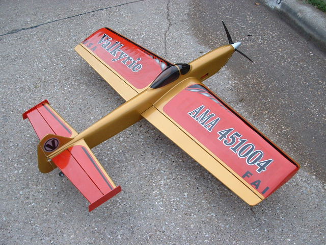
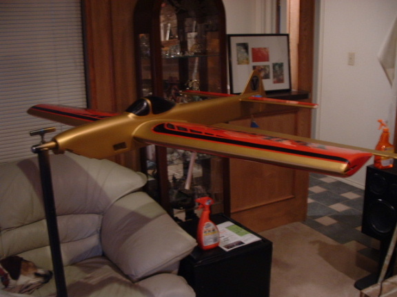
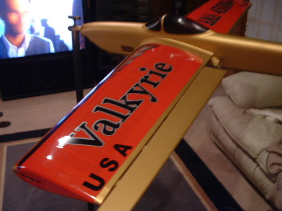
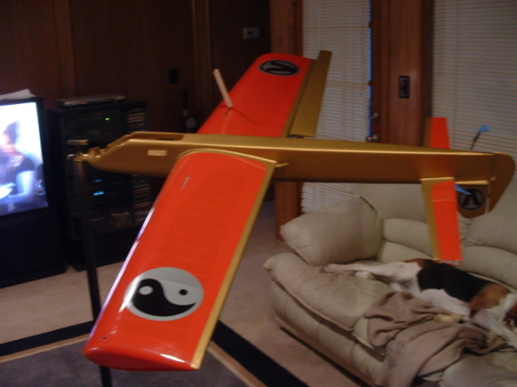
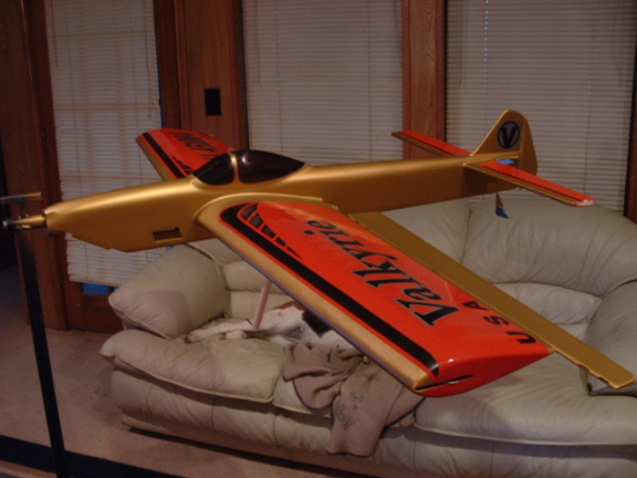
- Lastly, the Strega has a pretty “plane vanilla” shape. The fuselage is classic “lawn dart” and could lend itself to several types of styling’s. The cowl is supplied and is made of molded fiberglass. The wing has basically smoothed flat wing tips. The tail is very “squared off” and could also lend itself to a cosmetic makeover.
With that, the goal was to make some specific changes to compliment the original design.
- Convert the V-deflector nose design to accommodate a PA 75 with a rear exhaust muffler without losing the “boxed” fuselage design in the tank area.
- Include aluminum mounting pads for the engine.
- Create a new side profile that utilized as much forward side area as possible.
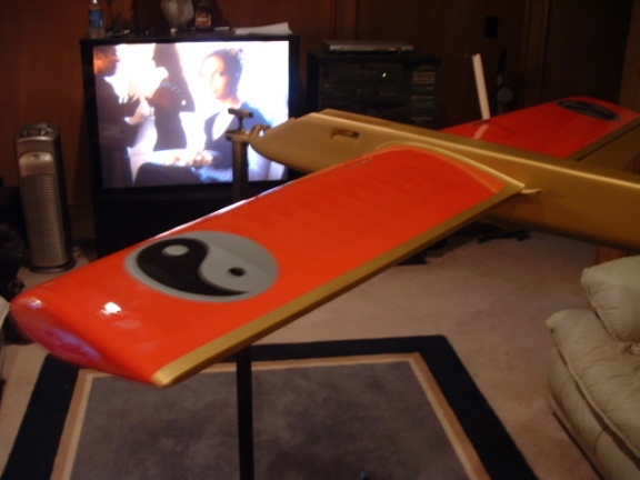
- Create a unique look.
- Replace the controls with my standard Tom Morris ball link system.
- Do as little work as possible.
- Don’t go overweight! The goal max weight was set at 70 OZ ready to fly.
About the same time I received the Strega, Brian Eather, a friend of mine from Australia sent me two new rear exhaust mufflers for the PA 75 for testing. I have been running the PA 75 on a tuned pipe, but I am convinced the big motor simply does not need the pipe to perform. The mufflers I received are actually made from mousse cans, but this is not obvious from looking at them, as the workmanship is typical Brian Eather (which is immaculate). The muffler that I chose was the smaller of the two, because it became apparent the larger is not a fit for the Strega nose. The small muffler is of typical Eastern European .60 sized stunt engine design, has a single baffle, and appears to give adequate performance on bench runs.
I have only had time to bench test the muffler, so in flight testing will ultimately prove the design. I am also interested in trying Randy Smith’s Aero Products rear exhaust muffler for the PA 75. I have heard through the grapevine that the Aero muffler works extremely well, and is Retro Discovery quiet at low RPM’s.
Brian also provided much needed help in providing a fuel tank that would not only fit into the design, but would hold 8 oz of fuel (this is the planned maximum fuel consumption of the PA 75). I have made my own metal tanks in the past, but decided to bug Brian for one of his units as he does a much better job of tank fabrication than me. Typically, I use plastic clunk tanks, but the Strega simply does not lend itself to the use of clunk tanks as the side vents locate the tank floor too close to the engine beams. The tank that Brian made is tapered from front to rear and actually uses a clunk fuel pickup. It fits like a glove.
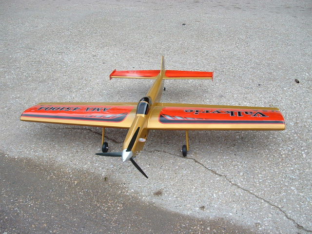
When the Strega finally arrived, all I could do was marvel at the construction. It appeared that nearly every piece of the plane was laser cut (excepting maybe the engine bearers). The wing sheeting is laser cut, and the wing is as straight as anything I can build, or frankly, can be built out of very unforgiving balsa wood.
The fuselage is a stiff a board. The stab and elevator consist of sheeted laser cut cores. The flaps and elevators are pre-hinged with real barrel hinges. All of the components are completely finished. The weight of the components appeared to be reasonable if the finish was minimized.
The only pieces scrapped from the ARC package were the flaps. I replaced the stock highly tapered flaps with ¼” c-grain flat stock. In retrospect, if I had been smart enough to paint the original units in the beginning, they would have been fine. I however, had no luck whatsoever trying to cover the stock units with film (more on that later).
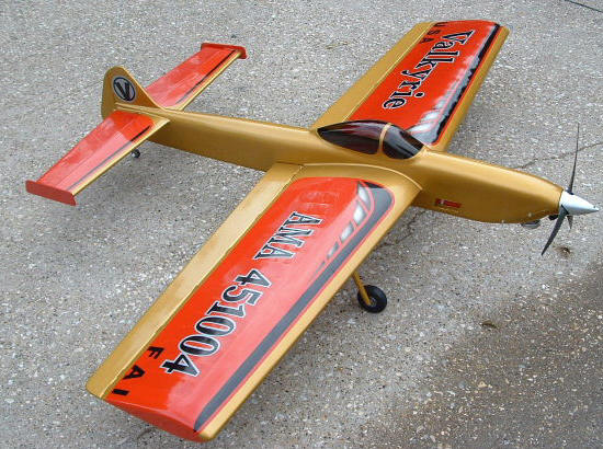
The first thing I did was removed the top block sheeting and structure back to the canopy firewall just behind the trailing edge of the wing. This eliminated the rear ward position of the canopy. The top block was replaced with a 1” black and then planed to a rough shape. To this new top block was fitted the largest WWII style canopy that I could get to fit. The idea was to create a sexier version of the Yatsenko stunter canopy look. I really like the canopy size and position as a result. The canopy was later dyed to a dark smoke.
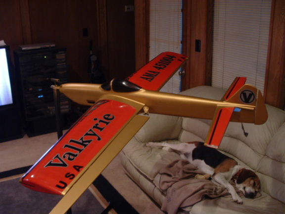
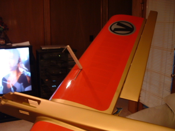
I tried several rudder shapes. The original simply looked too “it’s been done”.
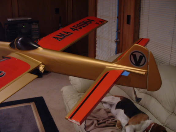
Eventually I settled on a rudder based on the shape used on my Solace design. Ironically the final result looks very much like a smoothed version of Jose Modesto’s Hawk.
None of the stock controls were used (Doug Moon produced all of the Tom Morris controls used in the plane). The bellcrank and all supporting structure were pulled from the wing. The bellcrank was replaced with a Tom Morris unit, using the standard “foam wing” suspended type installation method. The leadouts were already installed on the bellcrank and were fed through the wing to the Brodak adjustable leadout guide that is standard on the Strega. The stock 3/32” wire horns were replaced with 1 ¼” tall 1/8” wire units with a slider for the elevator, and the pushrods replaced with Central Hobbies carbon fiber pushrods with titanium ball link ends. The rear pushrod was manufactured in the turnbuckle configuration that can be easily adjusted without disconnecting the ball link from the control horn.
It was decided that the wing and tail would get a film finish. The film and balsa surfaces would then be finished n automotive basecoat and the whole airplane finished in auto clear. This would ensure that the weight would not get too far out of hand. This is where the project kind of ground to a halt…. I am not HORRIBLE at applying film, but then FILM IS NOT WHAT IT USED TO BE!!! I chose Monokote, which used to be the industry standard in film. I am here to say that modern Monokote is very disappointing. Finding a true color match was very challenging to say the least. The adhesive application was simply the worst I had ever seen, and in general the use of the film changed from roll to roll, and within each roll.
No kidding… I covered the wing 3 times before I got a decent application. The original flaps were so warped by the time the film actually stuck that I had to throw them away and make new ones. No matter what I do with film in the future, which I will continue to use, I will not be using Monokote. I will most likely use Ultracote from now on. Despite all the frustration with the film itself, I did manage to get a nice covering on the plane. It was decided in the end that it would be better to paint the flaps instead of cover with film.
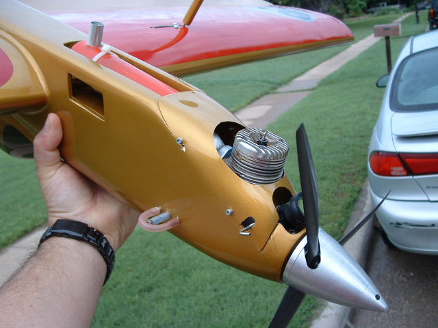
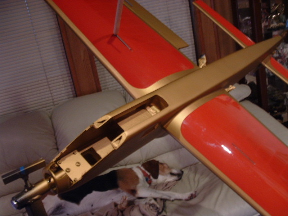
It was important that the front end be modified for aluminum engine pads. As a result the spinner had to be relocated. The also made it necessary to modify the cowl. The rear exhaust engine required that all of the V-deflector nose pieces removed. Once the angled plywood was removed the box was reformed using vertical balsa one either side and to the rear of the muffler box. The entire area around the muffler box was then covered in 6 oz carbon fiber matt. This is the same method used for pipe tunnels that I gleaned from Doug Moon. The final result was a nose that was again completely boxed and very stiff. I am very happy with the final result.
PART TWO:
Finishing begins!!!